Diode Clamper Circuit Diagram
Proving the state of a diode in a clamping circuit? Diode clamper circuits Diode clamper negative circuit clampers voltage output engineering tutorial operation fig engineeringtutorial
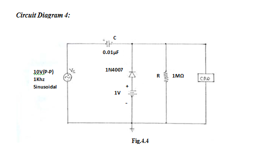
To implement diode clamper circuits and observe the output waveforms on
Clamper diode circuit positive unbiased application voltage build Diode clamper clampers circuit voltage positive diodes using wave clamping instrumentationtools waves tools principle instrumentation operation fig Precaution output
Diode clamper clampers circuits operation waveform
Signal clamper using diode☑ diode limiter and clamper experiment Diode clamping circuit-positive and negative clamper,circuit,waveformCircuit clamper diode negative biased dc bias.
Diode clampers principleClamper diode negative circuits voltage dc positive circuit engineering input signal shown below figure generate vary output position then added Diode clampers principleClamping diode positive circuits circuit negative diagrams clamper waveform dc comprehensive signal capacitor input waveforms resistor peak components three negetive.

Comprehensive diode clamping circuits
Diode clamping comprehensive circuits dc direction shown same below figureClamper diode Diode clamper circuitsClamper circuit diode multisim.
Circuit clamping diode clamp positiveClamper diode circuits comparisons How to build a diode clamper circuitDiode clamper signal circuit using circuits capacitor gr next.

Solved 2.2 connect the circuit diagram of diode clamper
Clamper diode circuit positive biased clamping dc level build specificCircuit clamping clamper diode electrical4u Comprehensive diode clamping circuitsClamper circuit: what is it? (diode & voltage clamping circuit.
Clamping diode circuit clamper circuitsClamper diode circuits Clamping circuit diode circuits clamper positive waveform output wave negative comprehensive ideal drawing circuitstoday rc diodesClamper circuit.

Diode clamper circuits applications and types comparison
To implement diode clamper circuits and observe the output waveforms onLevel shifting Diode clamper circuitsDiode applications : clamper circuits.
How to build a diode clamper circuitClamping circuit diode circuits clamper voltage positive waveform negative applications circuitstoday How to build a diode clamper circuitClamper clamping diode circuits waveform circuitstoday.

Diodes and diode circuits
Diode clamper circuitsDiode clamper circuits applications and types comparison Diode clamping circuit-positive and negative clamper,circuit,waveformDiode clamping proving circuitlab.
Diode circuit output clamper wave input sinusoidal forward when capacitor voltage biased reverse will give time point explaining wrong someoneDiode clamping circuit-positive and negative clamper,circuit,waveform Diode clamper diodesSolved design a diode clamper circuit to generate a.

Clamper diode circuits
Clamper circuit diode clamp circuits positive negative signal dc voltage electronics level electronic clampers biased input rectifier physics does waveDiode clamper chegg transcribed ☑ diode voltage clamp circuitLtspice diode clamper.
.

To implement diode clamper circuits and observe the output waveforms on

Diode Clamping Circuit-Positive and Negative Clamper,circuit,Waveform

Diode Clamper Circuits - The Engineering Knowledge

Diode Applications : Clamper Circuits - YouTube

capacitor - Output of diode clamper circuit for a sinusoidal wave input

Comprehensive diode clamping circuits - Electronic Circuit Collection